|
查看: 3726|回复: 6
|
pic24fj64ga002的uart问题
[复制链接]
|
|
|
本帖最后由 antiguilty 于 12-2-2011 12:31 PM 编辑
1。 应用 : 用电话控制我的机器人行走上下左右
2。用途: 学校作业
3。需要效果 :
用电话通过uart来控制我的单晶片(pic24fj64ga002)
4。遇到的问题:
我的uart好像没有反应
5。经过什么试验/检查 :
目前我是想试我的uart先,所以我写了一些code来把我的pic24接去我电脑的rs232,希望我电脑的hyperterminal能够跟我 的pic24沟通,但我的hyperterminal没有什么反应,真的不懂是我的hardware接错了,还是code有问题。还有,除了用hardware test 过,我也试过用proteus来test,一样是不能。
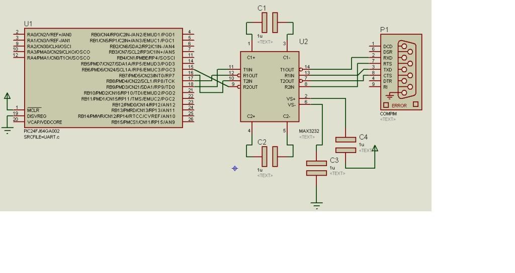
6. 电路图 :
7。 对于问题的头绪/见解:
没有头绪,因为我才刚接触这些东西,对不起
8。对于问题需要的解决方案:
希望我的pic24 uart能跟其他device沟通
还有我也不是很懂到底我的pic24接去电脑了没有,我是有用rs232 to usb adapter 的。我用virtual serial port software检查到我的电脑有两个physical port,com1 和 com3. 那我就把adapter 接去com1, 然后hyperteminal 接去com3,不知道这算不算接了呢?
以下是我的code:
<script src="http://pastebin.com/embed_js.php?i=AZF3bp4C"></script> |
|
|
|
|
|
|
|
|
|
|
|

楼主 |
发表于 12-2-2011 12:22 PM
|
显示全部楼层
对不起各位大大,我不懂如何用那个pastebin的网站。
所以我再放我的code上来:
/*
** Asynchronous Serial Communication
** UART2 RS232 asynchronous communication demonstration code
*/
#include <p24fj64ga002.h>
#define CTS _RB6 // Clear To Send, input, HW handshake
#define RTS _RB7 // Request To Send, output, HW handshake
#define TRTS TRISBbits.TRISB7 // Tris control for RTS pin
#define BRATE 34
#define U_ENABLE 0x8008 // enable UART, BREGH=1, 1 stop, no parity
#define U_TX 0x0400 // enable transmission, clear all flags
void initU2( void)
{
U1BRG = BRATE; // initialize the baud rate generator
U1MODE = U_ENABLE; // initialize the UART module
U1STA = U_TX; // enable the Transmitter
TRTS = 0; // make RTS an output pin
RTS = 1; // set RTS default status (not ready)
} //initU2
int putU2( int c)
{
while ( CTS); // wait for !CTS, clear to send
while ( U1STAbits.UTXBF); // wait while Tx buffer full
U1TXREG = c;
return c;
} //putU2
char getU2( void)
{
RTS = 0; // assert Request To Send !RTS
while ( !U1STAbits.URXDA); // wait for a new character to arrive
return U1RXREG; // read the character from the receive buffer
RTS = 1;
}// getU2
main()
{
AD1PCFG = 0x9FFF;
RPOR4bits.RP9R = 3; //set Tx to RP9
RPINR18bits.U1RXR = 8; //set Rx to RP8
RPOR3bits.RP7R = 4; //set RTS to RP7
RPINR18bits.U1CTSR = 6; //set CTS to RP6
char c;
// 1. init the UART2 serial port
initU2();
// 2. prompt
putU2('>');
// 3. main loop
while ( 1)
{
// 3.1 wait for a character
c = getU2();
// 3.2 echo the character
putU2( c);
} // main loop
}// main |
|
|
|
|
|
|
|
|
|
|
|
 发表于 13-2-2011 01:00 AM
|
显示全部楼层
发表于 13-2-2011 01:00 AM
|
显示全部楼层
首先确保MUC 去MAX232 的PIN 接对吗,如果有JTAG,可以用DEBUGGER 去看 UART2 的DATA REGISTER 有东西吗,
建议可以用 REALTERM, 免费下载、好用过HYPERTERMIAL
http://realterm.sourceforge.net/
请问你有INIT 你的MCU SYSTEM CLOCK 吗? |
|
|
|
|
|
|
|
|
|
|
|
楼主 |
发表于 13-2-2011 10:01 AM
|
显示全部楼层
本帖最后由 antiguilty 于 13-2-2011 10:03 AM 编辑
对不起canon forest大大,因为我是新手,所以不懂怎样init mcu system clock。但之前我试过用我的mcu来做其他project都没问题,从来弄过它的system clock。
jtag我也没有用过,但我会去了解看看是怎样使用的。 |
|
|
|
|
|
|
|
|
|
|
|
发表于 27-2-2011 12:04 PM
|
显示全部楼层
回复 4# antiguilty
现在点亮 led能吗? |
|
|
|
|
|
|
|
|
|
|
|
楼主 |
发表于 1-3-2011 05:40 AM
|
显示全部楼层
|
对不起,fritlizt大大,我的uart还是不成功,但现在我用了另外一个方法来用我的电话控制我的robot了,那就是dtmf。这个比较简单,不用经过uart就能把我的电话和pic连接起来。 |
|
|
|
|
|
|
|
|
|
|
|
发表于 2-3-2011 03:09 PM
|
显示全部楼层
对不起canon forest大大,因为我是新手,所以不懂怎样init mcu system clock。但之前我试过用我的mcu来做其 ...
antiguilty 发表于 13-2-2011 10:01 AM 
simulation的 comm不需要max232。用什么 compiler.?
如果是c30,c30的installation folder有详细的讲解如何使用uart library.你可以去看看。 |
|
|
|
|
|
|
|
|
|
| |
 本周最热论坛帖子 本周最热论坛帖子
|


 变色卡
变色卡 千斤顶
千斤顶 2093
2093  56
56